|
|
|
![]()
![]()
![]()
![]()
![]()
![]()
![]()


|
click on
your tip of interest: |
if
you find this content helpful then please show your support and vote
for my site by entering the top 100 R/C sites at the button above.
|

You will need:
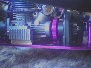
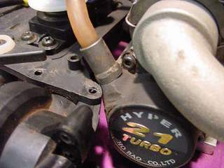
1) .21 powerplant: one w/ too much power will destroy your NMT, since it was not designed to handle these engines... so stay conservative. a highly recommended engine is the OFNA .21 hyper, it comes in both crankshaft versions, but the SG crankshaft is recommended since it will pose no problems w/ either single speed or two speed clutch bells.
If you would like to see more engine info, as well as a size comparison between the Evo II and hyper then go go to my Engine page.
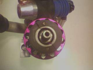
2) clutch nut: you will need to somehow secure the flywheel to the crankshaft. Make sure you get the right clutch nut for your engine. If you get the Hyper then you will need OFNA part # 10098, this set comes w/ shims as well as some spacer things for two speed clutch bells.
3) clutch: I used the stock plastic clutch when I broke in my engine, and as expected, it melted. I am now running this Kyosho clutch.
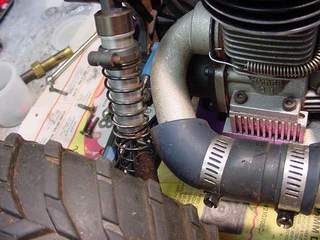
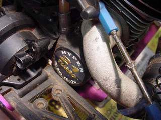
4) tuned pipe and header: a recommended pipe is the Duratrax EFRA part #DTXC9735, this same pipe is also made by Dynamite. You will also need a header and a rubber gasket, the Hyper comes with both. If you would like to learn more about tuned pipes then please read The Cold War on Tuned Pipes.
5) air filter: get yourself a proper air filter such as the ones made by Motorsavers. I am using the on-road filter part # MSFMS0221.
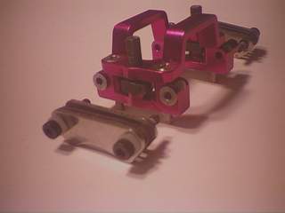
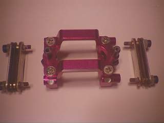
6) conversion kit: You can make your own mount and acquire a flywheel that works or you can just buy a conversion kit. There are two available kits out there: the New Era and Wolfpack Radicals part # WLF029. Although the Wolfpack kit isn't purple, the consensus is that it's better since the mount is adjustable (you can move the engine forward and backward). This is a huge plus for the Wolfpack kit. Also, the flywheel that comes in the Wolfpack kit is really small and makes it much easier to wedge that .21 powerhouse into your NMT. I can't say anything about the New Era kit other than it isn't adjustable.
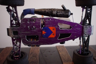
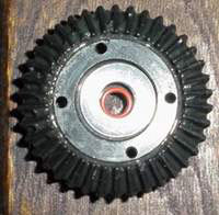
7) stronger parts: You can't just drop a huge powerplant into your NMT without upgrading the drivetrain and stiffening the chassis. For the drivetrain I recommend upgrading: Heavy Duty 38 Tooth Final Gear (front and rear); Heavy Duty 13 Tooth Final Gear (front and rear); Heavy Duty Diff Outdrive (front and rear). Front Center Universal Driveshaft and Rear Center Universal Driveshaft; and a slipper clutch would also be nice. Ditch the CVD's, stick with the dogbones because not only are they stronger, they are cheaper to replace. For the chassis I recommend upgrading to the Powerline 4 mm chassis and the Powerline Upper Deck. I prefer Powerline's chassis over Megatech's, as well as HPI's 2.5 mm racer chassis.
I prefer the aluminum upper deck that covers the entire upper deck over the graphite upper deck that retains the radio tray for the following reasons: 1) without the radio tray the chassis is truly tied to the upper deck for superior stiffness; 2) the throttle and steering servos are mounted to a fixed surface; 3) easier to deal with batteries without the removable radio tray; 4) graphite makes radio gear more susceptible to glitching.
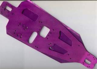
This is a scan of the Powerline chassis over the stock chassis. Although all the screw holes line up, my only gripe about this chassis is that the holes for the diff cases are a little larger and makes installing the diffs a little awkward. The Powerline chassis is also a little narrower so I fashioned a lexan guard to protect the battery. All in all, I think this chassis looks very sleek. Look on my NMT to see more of this chassis installed.
8) gearing: as you know, gearing is a balance of low end acceleration and high end top speed. Because the .21 has so much power, you have to gear it accordingly, and with the extra power you can tip the balance towards top speed. This can be done with a larger clutch bell, a smaller spur, or larger tires.
HPI's single speed clutch bells come in 11, 12, 13, 14, and 15 tooth sizes. But you can install a two speed clutch bell, and leave the first gear disengaged or grind the first speed off, and your choices increase to 16, 17, 18, 20, and a whopping 21 tooth gears. The OFNA clutch nut listed above comes with nifty spacers to allow the use of the larger two speed clutch bells on the crankshaft. You're going to need the slipper clutch in order to accommodate different size spurs. The spurs from HPI come in 37, 39, 41, 43, 44, 46, 49, and 52 tooth sizes. Note that the smaller the spur you use, the closer your engine must be to the center housing. You may need to notch your chassis to have more play and you may also run into conflicts with the center housing and the flywheel.
I am currently running a 16 tooth clutch bell (13/16 two speed clutch bell) and a 44 tooth spur. You're going to have to play around with the gearing, get something that suits your driving.
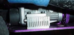
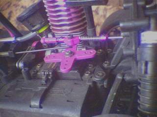
9) shims: if you use the Wolfpack Conversion kit you may need to raise the engine a bit. On my first attempt at making shims I used brass stock, hopefully available at your LHS or hardware store. The metal stock comes in a variety of thicknesses, I stacked 4 shims that were 2 mm thick and 33 cm long on each side of the engine. Using a shim rather than a washer is better because you want a larger area to displace the force. On my second attempt at making shims I used aluminum material from a hardware store, they turned out very nice and have a larger footprint making the OFNA hyper more stable. After filing them down they are 6mm tall. If you are crafty and have access to a machine shop then you can machine yourself a riser plate.
![]()
![]()
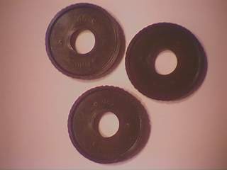
Wolfpack has made these nifty risers, they are 8mm tall, although I feel that 6mm would be perfect. Looks like I'm gonna file yours down Wolfgang.
![]()
9) linkage: I use an OFNA slide carb linkage part # 10725.
10) glow plug: the hyper really likes the MC-59 plug
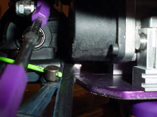
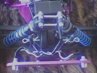
So once you've gotten all of the above parts you should install your heavy duty drivetrain with a smaller spur gear. Fitting the .21 engine into the NMT without the 2 speed is pretty easy. The engine won't have to be set as far back and therefore the engine's pull starter housing won't conflict with the a-arm, diff housing, upper deck, and right rear shock tower brace. If you are installing the .21 with the slipper clutch, then flip the slipper clutch around so that the spur gear is closer to the front. This will give you additional clearance. The engine will fit into the NMT, but its going to be a tight squeeze. Use shims to raise the engine a bit if you are using a pull start. Be sure to properly set your gears' backlash and tighten everything really good using lock-tite on all metal-on-metal screws. I use the front two sets of engine adjustment slots on my chassis to mount the engine with the slipper clutch and the rear two slots when using the 2 speed. You may also need to notch the slot to gain additional side-to-side adjustability.
 |
 |
 |
 |
 |
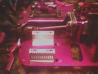 |
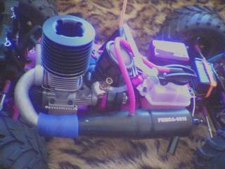
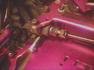
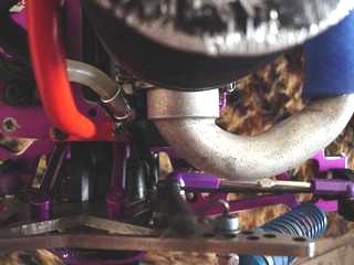
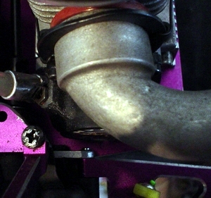
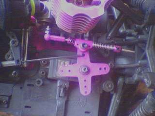
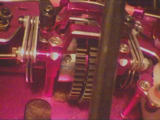
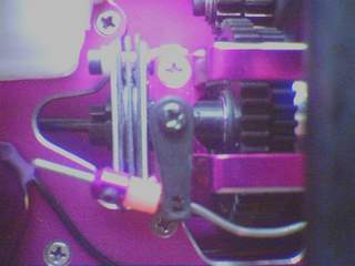
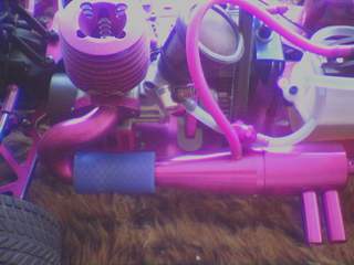
The picz below have been provided by MAXXED from the HPI forum. Take particular note of how far back his hyper has been mounted to accommodate the 2 speed. Notice the shaved material on the p/s housing? Better get that Dremel out.
 |
 |
 |
 |
![]()
![]()
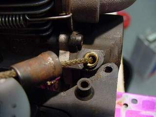
A side note for those of you using an OFNA hyper engine. It is a bear to get started for the first time, it won't be fun, but once it gets going it'll be much easier to re-start. You may try loosening the glow plug a few turns to relieve some of the compression. It will also help if you can hold the vehicle down properly while you crank on the pull-starter to get the hyper going. Starting the engine is the hardest part of this conversion.
I've started opening up my hyper and it screams. I haven't whipped out the radar gun yet so I can't tell you any speed info other than it seems like the hyper makes my NMT reach upper speeds faster. Not only do I get to speed faster, but with the taller gearing the top speed should undoubtedly be higher. As for fuel consumption, the hyper is not a guzzler. I get an amazing 13-15 minutes per 75 cc tank of 20% Trinity Monster fuel. A 125 cc tank may be desirable, but only if I could get it stuffed in without losing my dual brakes (look below). People have reported running 30% fuel in their hyper engines without having to add any head shims.
The damage with the .21 engine so far just consists of three fried spurs, all of which were second gear. I have never had a problem with the first speed.
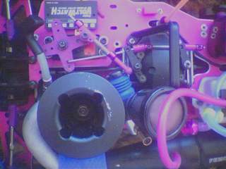
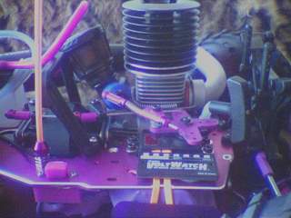
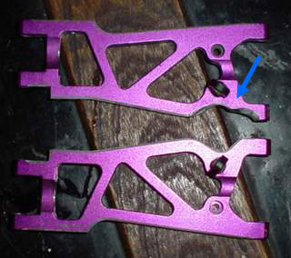
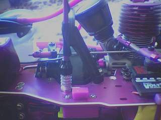
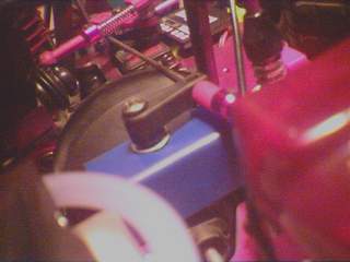
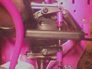
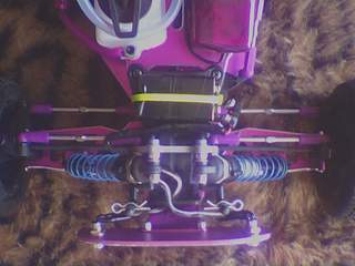
Here's some more conversion pics. Note the pics taken below are with the 2 speed installed so the engine is much farther back. Using the plastic arms in the rear causes a conflict with the pull starter. I solved this by using aluminum a-arms and shaving some material.
Did I miss anything? Did this text help you? e-mail kedar
Although I would have preferred mounting my Mugen Buggy wing farther to the rear using a bracket so as to move the wing back and mount it securely. Instead I have just compressed the Mugen mounts and forced them to fit the shock tower. The Mugen mounts are 32mm apart and the two screws that hold the rear shock tower braces are 21mm apart. So that's 11mm to squeeze... not too bad.
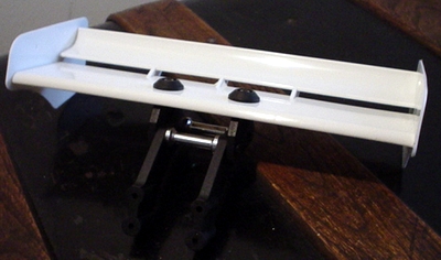
Mugen Wing Stay w/Body Mount MBX-4
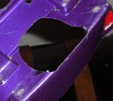
Here is the hole that I had to cut out of the body.
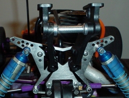
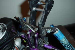
You can see the wing mounts compressed a bit. Only the lower two holes on the wing mounts are secured to the shock tower.
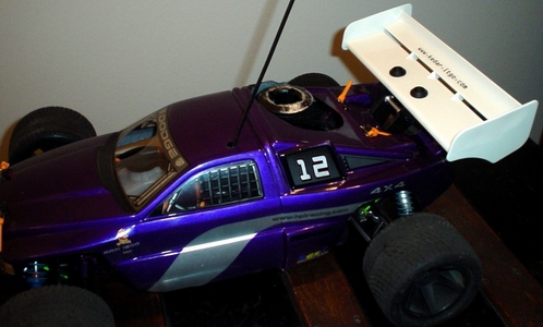
The finished
product.
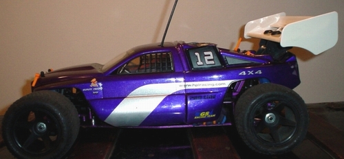
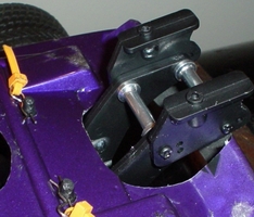
For additional support I strapped a zip tie from one of the wing mount supports to the shock tower. For other ideas you can see mtracer's web page.
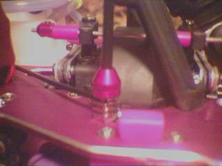
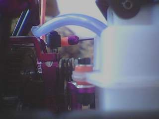
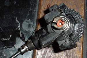
If you want ultimate protection on your r/c you'll use both a failsafe and a throttle return spring ("TRS"). The TRS is a mechanical safety device that will work whether your servo does or not, thereby protecting against runaways in instances where the battery disconnects, the throttle servo conks out, a servo or battery wire gets spliced, or if your ball cup pops off of the carb arm. You can install a spring to pull the servo horn, but this won't protect you if the ball cup pops off. In the case of rotary carbs you can install this spring on the carb arm itself. The slide carb presents a different difficulty in that the carb needs to be pulled towards the engine to close it. I used a regular hair band wrapped around the carb.
Make sure there is enough tension to pull the carb fully to the closed position. But note that when your engine is running the carb will be more willing to return to the closed position because of the engine's vibration.
Update: I have recently upgraded to a Hitec 645mg servo and it is much more resiliant to closing so I wrapped the spring around the carb assemble twice.
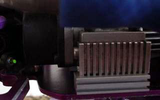
If your engine has a rotary carb then you will need to get a Throttle Return Spring kit from LOSI or Associated. They should come with an eyelet that you attach somewhere on your truck. You're going to have to look at your vehicle and try to attach the spring somewhere... use your ingenuity and be creative. Some people drill small holes in their heatsinks and mount the spring there. Others use the pull start ("p/s") housing, and yet others use the rear shock tower braces. You can attach a TRS to the throttle servo horn (the piece that spins), but this method of mounting is not as good as mounting the spring to the carb arm itself. Ideally you want a direct mechanical connection to the carb itself.
Slide Carb Linkage on Rotary Carb
You may want to install a slide carb linkage on your carb eventhough it is a rotary style. Its pretty easy and may increase your full throttle carb opening in the case that you can't get your FE to open up all the way using the stock linkage and a radio without end point adjustment (EPA). Be sure to install the ball end on the lower hole on the carb arm. I am considering modifying my FE's carb arm by drilling an even lower hole to install the ball end.
Below I am using OFNA slide carb linkage kit #10725. But you can check out all sorts of colors at ace-hobbies.
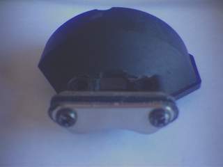
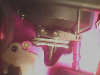
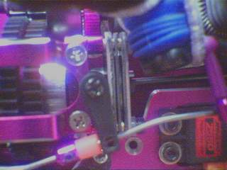
If you notice that your brake disk is rubbing against the flywheel then you may want to consider moving the brake to the front of the gear carrier. It's easy! First, remove the brake disk and install it on the other side of the gear carrier; second, remove the screws that retain the metal brake pads and install them on the other side of the plastic cap; third, make yourself a longer brake linkage using either piano wire or metal poles used for airplanes; and fourth, make a lexan splash guard.
The linkage will need to be slightly bent so that it clears the plastic cap that covers the spur gears. Your local hobby shop may be able to put a z-bend into the wire using a special tool, but I prefer bending it myself using pliers. The tool used at my LHS doesn't seem to make a bend that is accepted by my servo horn.
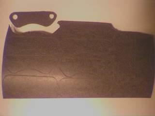
There is one problem that is presented with this conversion; namely, the risk of spilling / splashing fuel onto the brake disk (fuel will trash the brake). To remedy this problem, or at least ameliorate the risk, I have fashioned a piece of lexan to serve as a splash guard. I took a scrap piece of lexan that had a right angle and then drilled a hole in it. Mount the guard just below brake cam's arm.
You can swap the plastic or fiber disk for a metal brake disk. You will need to purchase a Kyosho Metal Brake Disk. You can check it out at Tower Hobbies.
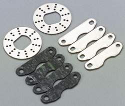
What you see above is what comes with the kit. You will also need a washer with a 3 mm inner diameter (large enough to go over the screw #Z282).
 |
1)
back side of Kyosho fiber pad and HPI brake plate |
Notice that the holes in the Kyosho brake plates are wider than the holes in the HPI brake plate? That means we won't be using the Kyosho brake plate; rather, we will use HPI's brake plate and Kyosho's fiber pads. Glue the fiber pad to the brake plate using a silicone adhesive such as Shoo-Goo. You may want to consider making your own brake pads using gasket material (detailed below). After you apply the adhesive you might want to carefully press the brake plate and the fiber pad with a vise, but be sure to pad both sides, in order to ensure a proper seal. Next, take a 5/32 drill and drill out the fiber material that is in the way.

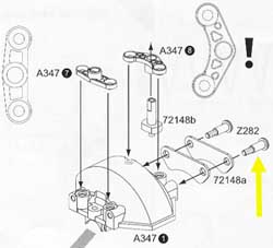
Here are the HPI brake plates and the Kyosho fiber pads installed. When I first assembled everything I did not install a washer at the above yellow arrow (in the scanned instructions). The brake cam part #72148b is not large enough to move the pads against the disk since everything is slimmer now. To compensate for this be sure to include a washer to give the cam some mechanical advantage. Use a nylon washer if possible because this will reduce your chances of having metal-on-metal interference.
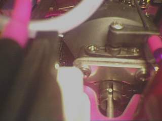
You'll see the washers installed in these photos. After installing them my brake performance increased dramatically. This conversion is an option for anyone who wants a non-stock braking system. I could have just purchased another fiber brake disk, but these are more susceptible to fade. Give your NMT an advantage and give it the power of metal brakes.
Note: There is another option for those who want metal disk brakes available from New Era. But I did not use this kit because it only comes with one disk and two pads, whereas the Kyosho set comes with two disks and four pads. Because using the Kyosho set only requires slight modification, I thought it would be best to get a better value. Also, the Kyosho metal disks look better.
You will need an additional brake cam as well as a set of metal brake plates (HPI part # 72148), two Z282 screws, and your brake of choice. I can't run a fiber brake disk in the rear because it significantly interferes with the flywheel. At least I have a little clearance between the metal brake disk and the flywheel. For dual brakes, simply install the brake in the front and rear of the center gear housing. The linkage will need a slight bend to make it slide properly. Adjust the brakes individually for full stopping power so when you combine the power of both brakes you'll stop with ease.
Idea: get an additional HPI brake plate and use silicone adhesive to glue it to the metal side of brake plate that is closest to the flywheel. Use this thicker pad instead of the washer. Everything would remain the same except that the brake disk would run a little bit closer to the rear of the truck and would therefore give the disk and the flywheel a little more clearance.
 |
 |
 |
 |
 |
 |
There is enough room on the HPI outdrive to install two metal disks per side, which means we can stack the brakes and have a quad brake set-up for ultimate stopping power. The trick is to space the pads out just right so that the brake cam can swivel to squish the brake plate. Note that using the stock gear carrier that the distance between the cam and the brake plate is longer in the front than it is in the rear. This means that for those of you using the stock configuration for the front brake will need to shim the front brake accordingly. A better idea is to bring the brake plate in the front (the one that the brake cam squishes) closer to the brake cam. This will give the cam more mechanical advantage, and also consistency. To do this you will need the Powerline center gear carrier. Then you will have to grind away the cylindrical knobs where the screws go to hold the brake plates in place. You grind just enough material to allow the brake plate closest to the brake cam to sit just as far as it does in the rear of the gear carrier.
To do this mod you will need a total of 4 brake disks, 4 HPI brake plates, 6 fiber brake pads, 2 brake cams, 2 brake arms, 5/32 brass tube, possibly some washers (I used Dubro 440 nylon washers). For the fiber pads, you can either use the Kyosho pads and modify them as explained in the Metal Brake Disk Conversion or you can make your own fiber pads as explained in Homemade Fiber Brake Pads.
After modifying my gear carrier I need to use an 8 mm piece of brass tubing to accommodate everything on each side. You may need to experiment finding the perfect size of tubing, and this will involve trial and error. The Powerline center gear carrier simplifies reassembly in that you install each brake assembly separately (the stock gear carrier will likely make reassembly very difficult). Although the washers aren't necessary, I like the idea of giving the brake plate farthest from each brake cam more surface area to press against. Also, the nylon hopefully secures the brass tube and keeps it from vibrating.
Update: I have been unable to get the brakes working without binding on one-another. Rather than having the middle fiber pad floating between the 2 brake disks, the solution is to use a fiber pad glued to each side of a metal brake plate. This will give the brake pad the support it needs and prevent it from binding. It seems that this can only be done on the front since there is not enough room on the rear outdrive to accomodate the additional parts.
Get some gasket material from an auto parts store, I used some rubberized fiber made by ROL Gaskets (#RK1016) and it comes in a roll that measures 10" x 26" x 1/32". Use the brake plate and a razor blade to trace an outline in the material, and then to cut the fiber pad to its shape. Make a whole bunch of pads, and then take a Dremel (if you have one) and use the sanding drum to give all the pads a nice smooth shape. Drill the holes on a bunch of pads at once by sandwiching the pads between the brake plates. The brake plates on both sides will act as a guide.
The benefit of making your own brake pads, as opposed to using the Kyosho ones in the case of my brake conversions above, is that the brake pad will go to the very bottom of the brake plate, resulting in more pad contact to the brake disk. I am currently testing out my homemade brake pads and they bring my truck to a brisk stop.
Below you'll see a pic of the material with many brake pads traced out on the gasket material next to a completed brake pad, as well as a pic showing the nice wear pattern on the pads after some use.
If anyone knows of a better material to use then please e-mail kedar.
Install o-rings or pieces of small slivers of fuel tubing to isolate your fuel tank from vibration.
If you run a CVEC pipe then you must keep the internal components clean or else the internal piston will not be able to move freely. I like to use denatured alcohol and cue tips to clean everything out. If you've never opened a CVEC pipe, or if you can never get it to thread together properly . . . then read on.
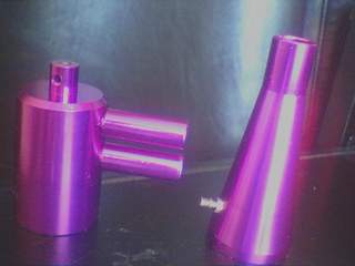
The CVEC pipe consists of two threaded pieces that screw onto an internal mechanism.
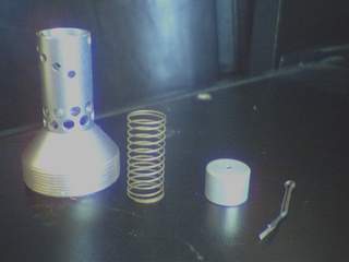
From left to right you'll see the threaded carrier that has exhaust holes, a spring, a piston, and a cotter pin. The manual tuning of the CVEC pipe is made by adjusting the pre-load on the spring by installing a cotter pin through one of 5 hole positions using the tuning adjustment holes. The 1st hole is the one that gives the most tension and it is the lowest of the holes pictured above, this hole will be the one closest to the engine. The 1st setting is advertised to provide the best fuel economy. The 5th hole is the one that gives the least tension and it is the highest of the holes pictured above, this hole will be the one farthest from the engine. The 5th hole is advertised to provide the best top end. You'll notice that the cotter pin is in the 5th hole above. I am happy with this setting.
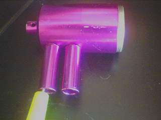
The CVEC is supposed to tune itself to the proper RPM, as your engine rev's faster there are more pulses emitted to the pipe and this causes the piston to move. The piston slides against the resistance of the spring and opens up additional exhaust ports (you'll see two rows of these exhaust ports in the pictures above). I don't know if this actually works, it sounds nice in theory. What matters is that I like this pipe because it works well with my Evo II, the deep exhaust tone sounds good, and the dual stingers look menacing.
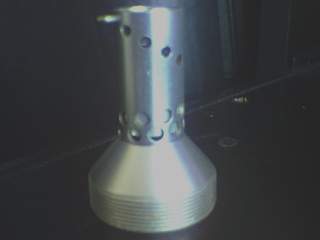
To properly reassemble the CVEC pipe you have to prevent the internal mechanism from rotating when you screw the pipe together. Here's what I do: 1) screw the internal mechanism into the front of the pipe and leave half of the threads visible, 2) take something long and thin and jam the internal mechanism using one of the tuning adjustment holes, 3) screw in the rear of the pipe. I am able to reassemble my CVEC pipe with the pressure nipple in the right place every time.
Here is the CVEC pipe mounted to a Big Tube T-Maxx Header with a Delcron reinforced exhaust coupler. The Evo II is quite happy with the CVEC, and so am I.

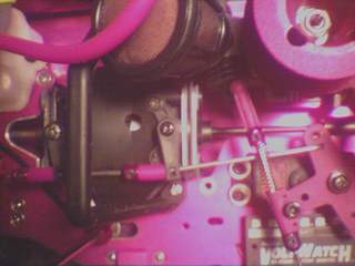
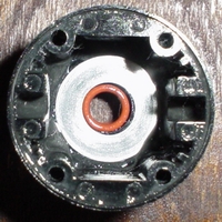
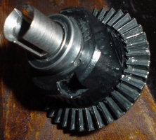
Do you want to prevent your NMT from unloading the engine's power to the wheel that does not have traction? You can fill the spider gear compartment (pictured above) with some differential fluid in order to slow the diff action down. I am using Kyosho 50,000 weight silicone fluid in the front diff and 10,000 weight Mugen silicone diff fluid in the rear diff. Since the buggies like to run a heavier fluid in their front diff, I figured NMT would like to do the same. The diff fluid is thicker than honey, and effectively prevents my NMT from unloading power to the free wheel. Some people opt to fill this compartment with grease, and yet others lock it entirely using JB Weld. I don't understand why people prefer to fill this compartment with grease rather than silicone, if anyone has ideas then e-mail kedar.
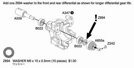
Be sure to include the M5 x 10 x .5 mm washer to remove unnecessary play between the crown and bevel gear. In addition to filling the spider gear compartment with silicone diff fluid, put a coat of grease on the 13 and 38 tooth final gears. Use the small o-rings part #6823 4.5x6.6mm, to seal the diff. Each o-ring goes into a recessed groove by the outdrives, two o-rings go into the diff case and two go into the 38 tooth gear, one on each side. Below you'll see a pic of the o-ring on each side of the HD 38t gear.
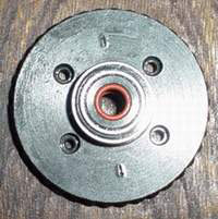
If you are running dogbones then be sure to install two o-rings in each front outdrive and one o-ring in each rear outdrive. This will prevent them from popping out. If you are using CVD's be sure to assemble them using red lock-tite. Note the butterecoat of grease on the 38t final gear.
The heavy duty 13 and 38 tooth gears are an expensive investment, but will ensure that you have a durable diff that can withstand the abuse of off-roading or a more powerful engine. The heavy duty outdrives are fairly inexpensive and are a good upgrade to consider. After my outdrives developed a notch I switched the right and left side for fresh material to wear away.
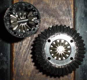
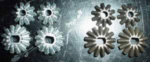
Another great upgrade is to use the spider gears from the new RTR3 part # 86014. The gears on the left are stock, and the ones on the right are the ones that HPI improved.
Note: If you use universal center shafts, then the only way you can have the brake in the front is if you have a HD 13t front diff gear.
|
you will need: |
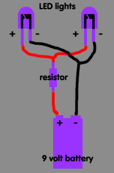 |
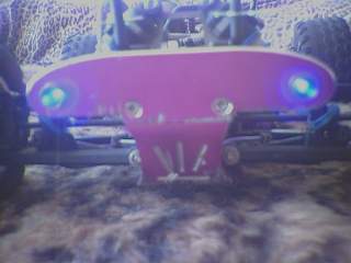
LED stands for Light Emitting Diode, and you can use these efficient bright lights to make lights for your r/c vehicle. These lights won't exactly brighten up the street and show you where you are going; rather, they will let you know where your ride is when you drive at night. Not only do they let you and others know where your ride is, but they look cool too. You will wire the circuit in parallel, meaning that the positive battery connection will make contact with the positive side of each LED light, and the negative battery connection will make contact with the negative side of each LED light. The alternative, which we will not be doing, is to wire them in series. This means that the positive battery connection would go to the positive of one LED, that wire would go to the negative on that LED, this would go to the positive of the other LED, then to the negative of that LED, and then lastly to the negative battery connection. You will be able to get all of the necessary parts at Radio Shack.
To begin your wiring harness, cut the positive wire on the 9 volt battery connector to the desired size. Leave the negative wire alone until later. Cut the excess wire on the resistor down to size and solder one end (it does not matter which, resistors don't care which direction the electricity will travel) to the positive wire on the battery connector. Now take two pieces of wire, as long as you think they need to be, and strip their ends. Take the end of each wire that will be the positive line and solder them to the other end of the resistor. Take the negative wire on the battery connector and cut it so that it is long enough to reach the negative wires. After stripping the negative battery connector wire, solder it to the negative side of each of the wires. While you solder wires together you may want to consider where the shrink wrap will be installed because you'll find yourself unable to put the shrink wrap over the wires as your wiring harness takes form. If you've done everything right then the only thing that remains to be done is to solder the LED lights to the wiring harness. If you are using light buckets, take notice of how they hold the lights. After all, you don't want to solder the LED's only to realize that you can't install them in the buckets.
Soldering may be tricky, particularly for beginners, and trying to solder two wires to a third may take a little patience. Stick with it, let the soldering iron get hot, and don't burn yourself. The above instructions could be modified to include a switch. I prefer not to use one since it would only make for an ugly wiring harness and something else to worry about. Remember, the less soldered connections, then the more secure and durable your circuit will be. I turn the lights on and off simply by the 9 volt battery connection. I'm sure this isn't the only place you've seen the application of KISS (Keep It Simple Stupid). If you choose to include a switch then just install it somewhere on the positive side of the circuit to prevent power flow from getting to the lights.
Too much resistance and
your lights won't shine bright. Too little and you will blow your LED's. Here
is the formula to use to figure out the proper resistor: r
= v / i Since my blue LED's are 5 volts and have a 30mA draw (which
is .03A) this is how to use the formula for a parallel circuit:
v = 9 volts - 5 volts = 4 volts (this is how
much the resistor must drop the voltage from the 9 volt battery)
i = .03 + .03 = .06 (since I am running 2 blue
LED's I added the total draw)
r = 4 / .06 = 66.66666 (so I would need to find
a resistor as close to this figure as possible)
a great source for info theLedLight.com
A more complicated 6 LED wiring system soon to come!
To keep dirt and debris away from your precious spur gears you ought to use a spur guard. You can either use the one that is provided in the wheel well of HPI bodies, or you can make your own.
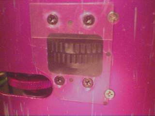
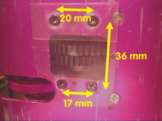
This piece of lexan is 45 mm wide and 55 mm long. The two holes on the bottom (rear) are 17 mm apart and the top (front) holes are 20 mm apart. The distance between the top and bottom rows is 36 mm.
I used an additional piece of lexan towards the front in order to give the spur gear more clearance.
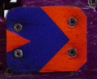
The above piece is my current spur protector. It is lexan material from the rear engine hole of a recent body. I used an additional piece of painted lexan (like that depicted above) between the piece shown and the chassis.
 |
|
Replace the four bushings, part numbers A396(1), with 4 x 8 x 3 unflanged bearings. These little bearings could be expensive, but will surely smoothen up your steering. I'm told that xtm part #256960 is a good and cheap source for these bearings.
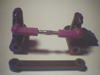
There is a lot of play in the steering, and most of it can be attributed to part number A396(4). You can stiffen up the steering by replacing the plastic piece with a 1 1/2 inch titanium turnbuckle and RPM heavy duty ball ends. You will need to replace the screw Z282 with a ball end such as Z136. Be sure to carefully adjust the turnbuckle so that it measures 48 mm (center to center). Quick tip, you can also measure from the bottom of one cup to the bottom of another to achieve more accurate results.
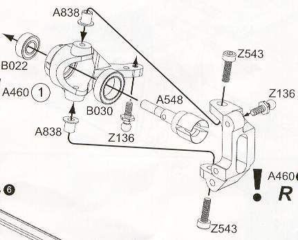
You can also tighten up a bit of your steering by gluing the flange part number A838 with some CA glue to the steering knuckle. When you re-tighten the Z543 allen screw, don't crank it down too hard or else there will be too much resistance.
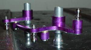
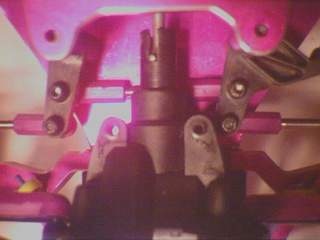
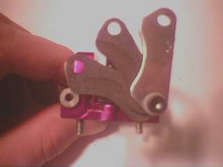
I've recently picked up the Powerline aluminum steering assembly and I am very impressed. This is a great hop-up. The stock design uses rather weak flange shafts in the bell cranks, the Powerline design is much more solid. The pic above shows the proper way to assemble it. It comes with nylon bushings that can be replaced by 5 x 8 x 3 unflanged bearings.
This is a very simple mod that will improve your NMT by reducing friction and maintenance, as well as adding reliability. Replace the needle bearing in the clutch bell with two flanged 5 x 8 mm bearings (for the ends) and two unflanged 5 x 8 mm bearings (for the inside). Use three unflanged bearings for the two-speed clutch bells.
LED lights can be installed cleanly using buckets. You can either use a blister pack (plastic packaging) or you can make the bucket yourself.
| you will need: clay lexan silver paint silicone-based adhesive heat gun / hair dryer dremel w/ attachments drill pencil eraser / brush |
 |
I used some clay from an arts and crafts store to make an impression of my body's inside. You can either let the clay air dry for 48+ hours, or you can bake it in the oven for quicker results.
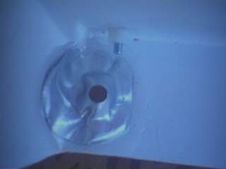
Once the clay impression is dry use a Dremel tool to cut a hole. If you're too anxious you may notice that some of the interior clay isn't completely dry, in this case just give it a little more drying time. Make sure the hole you make is deep enough to accommodate the LED light. Below you'll see the clay impressions that I used.
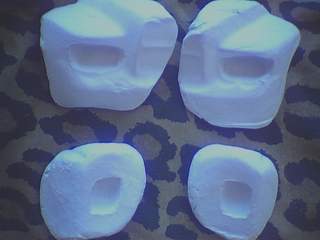
Once you are happy with your clay impression, its time to form the lexan to its proper shape. Place a square of lexan over the mold, and heat it up with a heat gun or hair dryer, you'll notice the lexan get melty and become very malleable. Use a brush or a pencil eraser to push the plastic into the mold. Take your time to avoid wrinkles. You'll have to be patient to get the result you want.
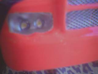
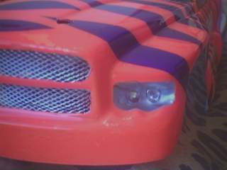
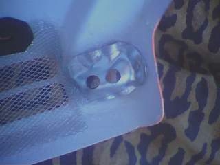
Once your light bucket is formed spray the back of it in silver, cut it out and drill the proper holes. Secure it to your body using the silicone adhesive such as Shoo-Goo or Goop. Before painting my body I masked off the headlight area, and then put the headlight decal over the clear space. I did not like how the headlights looked shining though the decals so I removed them.
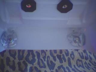
Below: the front buckets installed w/ close-up.
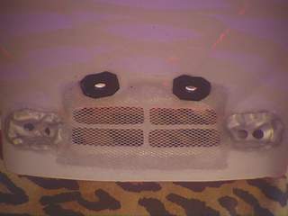
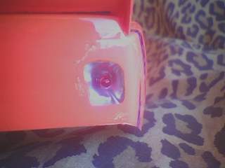
Below: the rear buckets installed w/ close-up.
Interactive: Move your mouse over the images below to see the LEDs shine.